|
RAD Studio (Common)
|
UML 2.0 State Machine Diagram Definition
|
RAD Studio (Common)
|
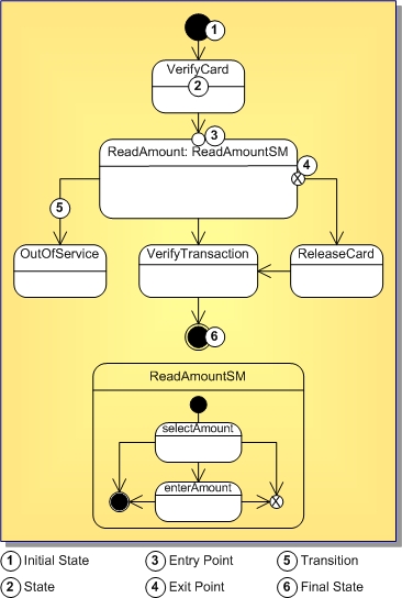
States are the basic units of the state machines. In UML 2.0 states can have substates.
Execution of the diagram begins with the Initial node and finishes with Final or Terminate node or nodes. Please refer to UML 2.0 Specification for more information about these elements.
State Machine diagrams describe the logic behavior of the system, a part of the system, or the usage protocol of it.
On these diagrams you show the possible states of the objects and the transitions that cause a change in state.
State Machine diagrams in UML 2.0 are different in many aspects compared to Statechart diagrams in UML 1.5.

|
Copyright(C) 2008 CodeGear(TM). All Rights Reserved.
|
|
What do you think about this topic? Send feedback!
|