UML 2.0 Class diagrams feature the same capabilities as the UML 1.5 diagrams.
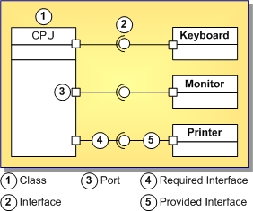
The UML 2.0 class diagrams offer new diagram elements such as ports, provided and required interfaces, and slots.
According to the UML 2.0 specification, an instance specification can instantiate one or more classifiers. You can use classes, interfaces, or components as a classifier.
A class implements an interface via the same generalization/implementation link, as in UML 1.5 class diagram. In addition to the implementation interfaces, there are provided and required interfaces. Interfaces can be represented in class diagrams as rectangles or as circles. For the sake of clarity of your diagrams, you can show or conceal interfaces.
UML 2.0 class diagram supports the ball-and socket notation for the provided and required interfaces. Choose Show as circle command on the context menu of the interface to obtain a lollipop between the client class and the supplier interface.
The figure below shows a class diagram with some of the new elements.

|
Copyright(C) 2009 Embarcadero Technologies, Inc. All Rights Reserved.
|
|
What do you think about this topic? Send feedback!
|