|
RAD Studio (Common)
|
|
RAD Studio (Common)
|
Using Modeling, you can create language-neutral class diagrams in design projects, or language-specific class diagrams in implementation projects. For implementation projects, all diagram elements are immediately synchronized with the source code.
A class diagram provides an overview of a system by showing its classes and the relationships among them. Class diagrams are static: they display what interacts but not what happens during the interaction.
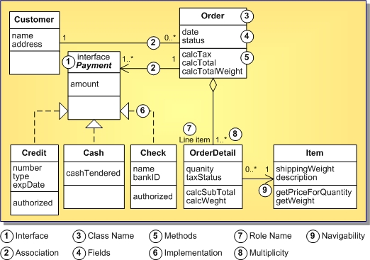
UML class notation is a rectangle divided into three parts: class name, fields, and methods. Names of abstract classes and interfaces are in italics. Relationships between classes are the connecting links.
In Modeling, the rectangle is further divided with separate partitions for properties and inner classes.
The following class diagram models a customer order from a retail catalog. The central class is the Order. Associated with it are the Customer making the purchase and the Payment. There are three types of payments: Cash, Check, or Credit. The order contains OrderDetails (line items), each with its associated Item.

There are three kinds of relationships used in this example:
|
Copyright(C) 2009 Embarcadero Technologies, Inc. All Rights Reserved.
|
|
What do you think about this topic? Send feedback!
|